Repair/Overhaul of PowerMac G5 Liquid Cooling System and CPU Boards
2.7 GHz Dual-CPU G5 built May 2005 - Delphi LCS
By Bill S.
Posted: July 22, 2010
(This is Page 5 of the 6 page article)
Reassembly
33) With new O-rings in the grooves of the modules, they were reassembled/installed into the LCS. When tightening the four flat-head Philips screws, they should be sequenced across diagonals in steps, to keep even pressure on all sides of the O-rings until they are sealed. Do not overtighten these screws; I have no torque numbers, but they compress the O-rings, and should be tight but not forced. Figure 35 shows the installed HTMs after cleaning.
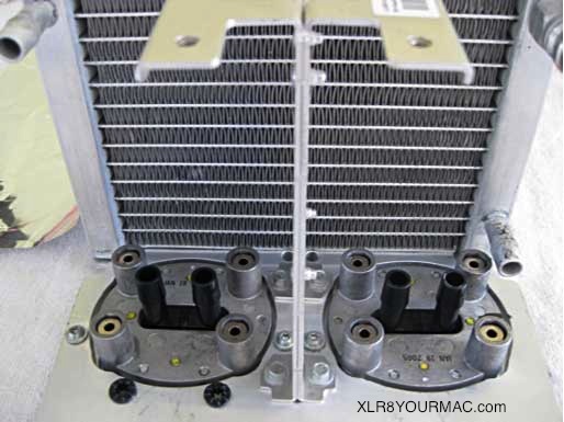
Figure 35. Heat Transfer Modules Installed After Cleaning
34) Figure 36 shows the beginning of hose re-installation. Figure 37 shows the radiator output path reinstalled.
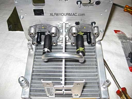
Figure 36. Jumper Hose Reinstalled
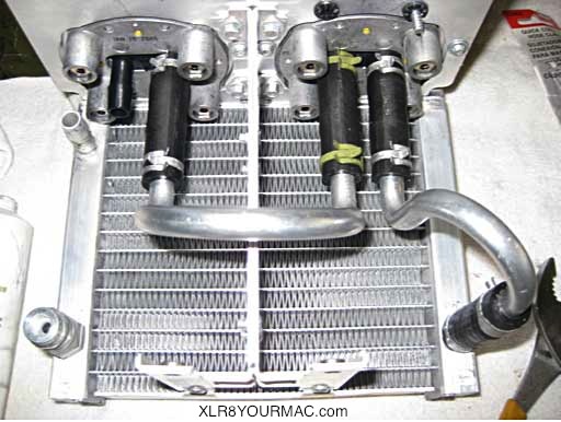
Figure 37. Radiator Output Connection Reinstalled.
35) Figure 38 shows initial re-installation of the coolant pump. Figure 39 shows the pump input and output hoses reconnected.
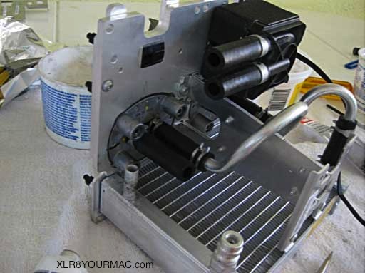
Figure 38. Coolant Pump Re-attached
36) In Figure 39, note the upward direction of the arrow embossed on the pump case (right port). This is the coolant flow direction. Hot coolant flows into the radiator at the top of the picture. Cooled fluid at the bottom of the radiator flows out and into the first heat transfer module. It then flows into the second module, and then back into the pump. The pump therefore is always pumping the hottest coolant. This is backwards from a normal auto cooling system flow, which operates the coolant pump at the coolest possible temperatures.
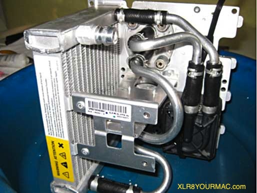
Figure 39. Complete Coolant Path Reassembled
37) My method of refilling the coolant was as follows:
- Disconnect the hose at the radiator input port (furthest upper hose in Figure 39).
- Insert the plastic coolant bottle's tapered cap, opened, upside down, into the temporarily bent-up upper hose connected to the coolant pump output.
- Squeeze the bottle. This forces coolant into and through the pump, through both heat transfer modules, and into the bottom of the radiator. Continue squeezing until the radiator fills and coolant appears at the top (input) port of the radiator.
- Pull the bottle out of the hose, which should be full to the end, quickly lower it into position and push it onto the radiator input port
If there is air remaining in the system, it should be a very small amount (see discussion at end of this article).
38) Before reinstalling the CPU boards, I put thermal grease on the mating surface (raised boss) of the heat transfer modules. You can see that in Figure 40. The amount you see there is apparently too much!
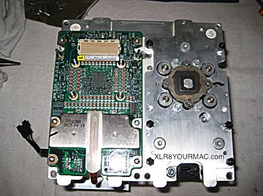
Figure 40. CPU A Reinstalled - Thermal Grease on CPU B Heat Transfer Module
39) When reinstalling a CPU board to the LCS, be careful of the Memory Controller heat sink and pipe! Visually line up the four holes for the Allen screws and lower the board carefully while keeping them aligned. Then put the four Allen screws in by hand and hand-tighten them, fairly easy because the screws have raised heads. Then put in the six Philips screws using a screwdriver, but turn them in lightly. Then go back to the Allen screws and screw them down in steps across diagonals to keep the mating surfaces flat. This closes the heat transfer path between the CPU chip and the LCS HTM. Finally, tighten the six Philips screws.
40) When both CPUs are installed onto the LCS, reattach the bottom plate (Figures 8 through 10), being careful to guide the Memory Controller heatsink into the bottom plate's clips as you line up the mounting holes. Install and tighten the two Allen screws.
41) The CPU/LCS asssembly is now ready to be reinstalled back into the computer. Revisit the "ifixit" link in paragraph 10) above, and run backwards from their step 17 to reinstall the assembly. Be very careful to visually line the assembly up with the guide pins in the computer before pressing it down to engage the CPU connectors!
Tighten the eight Allen screws carefully at the locations shown in their step 14. Do not overtighten!
= Continue to Page 6 =
Index of PowerMac G5 LCS Repair Article
Page 1 | Page 2 | Page 3 | Page 4 | Page 5 | Page 6
|
