The Source for Mac Performance News and Reviews Dual G4/500 CPU Module Bus/CPU Ratio Settings | |
| |
(The G4 CPU module speed settings info used for this mod are from the Nov. 30th, 1999 article on the single G4/AGP CPU module by Michiro Isobe.)
"Busy running tests now, just OC'd my 500 Mystic to 550 by changing jumpers from 5x to 5.5x. Seems stable so far, compressed and opened .smi files, ran Gauge pro memory test for 5 min with no faults. Also had several apps open, leaving 5.3 MB of RAM unused out of 348with no probs so far.
Using Table 14 from the Motorola 7400 (G4) PDF file (http://www.mot.com/SPS/PowerPC/teksupport/teklibrary/specs/7400_hs.pdf) on PLL settings, I created the following (simplified) table which identifies the resistor areas populated for various Bus/CPU ratio settings. (A zero "0" means a resistor is present at the location specified (at positions 0,1,2,3 respectively). Since the low end dual G4 system is a 450MHz I didn't bother to show settings below 4.5x ratio, and only show ratio settings as high as 6.5x (650mhz with a 100mhz bus speed). Remember these are just settings, and that it's unlikely any current G4 CPU would run even 600mhz reliably (some have reported running 600Mhz on a single CPU with voltage tweaks and additional cooling). It's important to remember even one step up (50Mhz boost) may not be reliable on your CPU. Mods like this are only for those that are willing to risk damage to the module and failure.
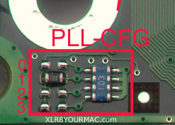
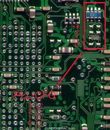
 Resistor locations for PLL_CFG 0, 1, 2 and 3 are shown in the photos below.
(Closer Look at Top Side area)
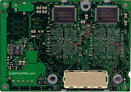
(Closer Look at Back Side area) Note: Traces (circuit paths) on the surface of the board are only protected by a thin solder mask, so if you scratch the solder mask coating over a trace (with a soldering iron for instance), a solder bridge could then cause an undesired short-circuit. (Which could damage the CPU or other module components.)
| |
= Other Site Topic Areas =
| |
© 2000, all rights reserved. |